Suzuki Grand Vitara JB627. Manual — part 2
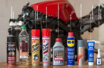
• Be sure to observe following instructions
when handling service materials such as
fuel, oil, fluid, coolant, grease, sealant,
thread lock cement, etc. Otherwise, your
health may be ruined.
– Whenever handling any of these service
materials, wear safety glasses to protect
your eyes. If it gets into your eye, it may
cause inflammation.
– Whenever handling any of these service
materials, wear moisture-proof gloves to
protect your skin. If it adheres to your
skin, it may cause inflammation.
– Do not swallow any of these service
materials. It would cause diarrhea or
nausea.
– Keep all these materials out of children’s
• Make sure the bonnet is fully closed and
latched before driving. If it is not, it can fly
up unexpectedly during driving,
obstructing your view and resulting in an
accident.
• Before starting any service work, cover
fenders, seats and any other parts that are
likely to get scratched or stained during
servicing. Also, be aware that what you
wear (e.g. buttons) may cause damage to
the vehicle’s finish.
• When performing service to electrical parts
that does not require use of battery power,
disconnect the negative cable of the
battery.
• When disconnecting the negative cable
from the battery, be careful to the
following.
– Check and record DTCs in ECM and
TCM if necessary before disconnecting.
– Record displayed contents of the clock
and/or audio system, etc. before
disconnecting and reset it as before
after connecting.
– For vehicle equipped with electric
throttle body system, perform electric
throttle body system calibration
referring to “Electric Throttle Body
System Calibration in Section 1C” after
reconnecting the negative cable to the
battery.
– For vehicle equipped with power sliding
roof (sunroof), initialize sliding roof
position data in motor unit by
performing “How to reactivate the
system to prevent being pinched by the
sunroof” in Sunroof section of Owner’s
manual.
• When removing the battery, be sure to
disconnect the negative cable first and
then the positive cable. When
reconnecting the battery, connect the
positive cable first and then the negative
cable, and replace the terminal cover.
Источник
Suzuki Grand Vitara JB627. Instruction — page 6
There are two kinds of colored wire used in this vehicle.
One is single-colored wire and the other is dual-colored
(striped) wire. As the color symbol, the single-colored
wire uses only one, three or five alphabets (i.e. “G” or
“GRN”); the dual-colored wire uses two color symbols
combination (i.e. “G/Y” or “GRN/YEL”). The first symbol
represents the base color of the wire (“G” or “GRN” in
the figure) and the second symbol represents the color
of the stripe (“Y” or “YEL” in the figure).
Metric Fasteners
Most of the fasteners used for this vehicle are metric. When replacing any fasteners, it is most important that
replacement fasteners be the correct diameter, thread pitch and strength.
Fastener Strength Identification
Most commonly used metric fastener strength property classes are 4T, 6.8, 7T, 8.8 and radial line with the class
identification embossed on the head of each bolt. Some metric nuts will be marked with punch, 6 or 8 mark strength
identification on the nut face. Figure shows the different strength markings.
When replacing metric fasteners, be careful to use bolts and nuts of the same strength or greater than the original
fasteners (the same number marking or higher). It is likewise important to select replacement fasteners of the correct
diameter and thread pitch. Correct replacement bolts and nuts are available through the parts division.
Metric bolts: Identification class numbers or marks correspond to bolt strength (increasing numbers represent
increasing strength).
Источник
Suzuki Grand Vitara JB627. Instruction — page 11
0B-14 Maintenance and Lubrication:
Tightening Torque Specifications
Reference:
For the tightening torque of fastener not specified in this section, refer to “Fastener Information in Section 0A”.
Special Tools and Equipment
Recommended Fluids and Lubricants
Refer to “Engine Oil and Filter Change”.
Engine coolant
(Ethylene glycol base coolant)
“Antifreeze / Anticorrosion coolant”
Refer to reservoir cap of brake master cylinder.
Refer to “Manual Transmission Oil Change in Section 5B”.
Refer to “Transfer Oil Change in Section 3C”.
Differential oil (front & rear)
Refer to “Front Differential Oil Change: Front in Section 3B”, or “Rear
Differential Oil Change: Rear in Section 3B”.
Automatic transmission fluid
Refer to “A/T Fluid Change in Section 5A”.
Engine oil or water resistance chassis grease
Hood latch assembly
Key lock cylinder
09915–47320
Oil filter wrench cap (79 mm)
)
Precautions for Engine. 1-1
Engine and Emission Control System
Electronic Control System Location . 1A-23
Engine Symptom Diagnosis . 1A-51
Malfunction Indicator Lamp Does Not Come
Malfunction Indicator Lamp Remains ON after
DTC P0031 / P0032: HO2S Heater Control
Circuit Low / High (Sensor-1, Bank-1). 1A-61
DTC P0037 / P0038: HO2S Heater Control
Circuit Low / High (Sensor-2, Bank-1). 1A-65
DTC P0051 / P0052: HO2S Heater Control
Circuit Low / High (Sensor-1, Bank-2). 1A-68
DTC P0057 / P0058: HO2S Heater Control
Circuit Low / High (Sensor-2, Bank-2). 1A-72
DTC P0101: Mass Air Flow Circuit Range /
DTC P0102 / P0103: Mass Air Flow Circuit
DTC P0107 / P0108: Manifold Absolute
Pressure Sensor Circuit Low / High Input . 1A-78
DTC P0111: Intake Air Temperature Sensor
Circuit Performance . 1A-81
DTC P0112 / P0113: Intake Air Temperature
Sensor Circuit Low / High Input. 1A-82
DTC P0116: Engine Coolant Temperature
Circuit Range / Performance. 1A-84
DTC P0117 / P0118: Engine Coolant
Temperature Circuit Low / High Input . 1A-86
DTC P0122 / P0123: Throttle Position Sensor
(Main) Circuit Low / High Input. 1A-87
DTC P0133 / P2A00: O2 Sensor Circuit Slow
DTC P0134: O2 Sensor Circuit No Activity
DTC P0137 / P0138: O2 Sensor Circuit Low
Voltage / High Voltage (Sensor-2, Bank-1) . 1A-93
DTC P0140: O2 Sensor Circuit No Activity
Detected (Sensor-2, Bank-1) . 1A-95
DTC P0153 / P2A03: O2 Sensor Circuit Slow
DTC P0154: O2 Sensor Circuit No Activity
DTC P0157 / P0158: O2 Sensor Circuit Low
Voltage / High Voltage (Sensor-2, Bank-2) . 1A-101
DTC P0160: O2 Sensor Circuit No Activity
Detected (Sensor-2, Bank-2) . 1A-103
DTC P0171 / P0172: System Too Lean / Too
Rich (Sensor-1, Bank-1) . 1A-105
DTC P0174 / P0175: System Too Lean / Too
Rich (Sensor-1, Bank-2) . 1A-108
DTC P0222 / P0223: Throttle Position Sensor
(Sub) Circuit Low/High . 1A-111
DTC P0300 / P0301 / P0302 / P0303 / P0304
/ P0305 / P0306: Misfire Detected . 1A-113
DTC P0327 / P0328: Knock Sensor Circuit
DTC P0335: Crankshaft Position Sensor
DTC P0336: Crankshaft Position Sensor
Circuit Range / Performance. 1A-119
DTC P0340: Camshaft Position Sensor
DTC P0341: Camshaft Position Sensor
Circuit Range / Performance. 1A-122
DTC P0401 / P0402: Exhaust Gas
DTC P0403: Exhaust Gas Recirculation
DTC P0420 / P0430: Catalyst System
Efficiency Below Threshold (Bank-1 / -2) . 1A-127
DTC P0444 / P0445: EVAP Emission System
Purge Control Valve Circuit Open / Shorted .1A-129
DTC P0462 / P0463: Fuel Level Sensor
DTC P0480 / P0481 / P0482: Fan 1 / Fan 2 /
Fan 3 Control Circuit . 1A-133
Pressure Sensor Circuit Low / High . 1A-136
DTC P0601 / P0602 / P0607: Internal Control
DTC P0616 / P0617: Starter Relay Circuit
Valve Control Circuit Low / High . 1A-142
DTC P1107 / P1108: Manifold Absolute
DTC P1510: ECM Back-Up Power Supply
Circuit Range / Performance. 1A-147
DTC P2102: Throttle Actuator Control Motor
DTC P2103: Throttle Actuator Control Motor
DTC P2108: Throttle Actuator Control Module
DTC P2119: Throttle Actuator Control Throttle
Body Range / Performance. 1A-152
DTC P2122 / P2123: Pedal Position Sensor
(Main) Circuit Low / High. 1A-153
DTC P2127 / P2128: Pedal Position Sensor
(Sub) Circuit Low / High . 1A-155
DTC P2135: Throttle Position Sensor (Main /
Sub) Voltage Correction. 1A-157
DTC P2138: Pedal Position Sensor (Main /
Sub) Voltage Correction. 1A-159
DTC P2195 / P2196: O2 Sensor Signal Stuck
Lean / Stuck Rich (Sensor-1, Bank-1). 1A-161
DTC P2197 / P2198: O2 Sensor Signal Stuck
Lean / Stuck Rich (Sensor-1, Bank-2). 1A-163
DTC P2227/ P2228 / P2229: Barometric
Pressure Circuit Malfunction . 1A-165
DTC P2237: O2 Sensor Positive Current
Control Circuit / Open (Sensor-1, Bank-1) . 1A-166
DTC P2238 / P2239: O2 Sensor Positive
DTC P2240: O2 Sensor Positive Current
Control Circuit / Open (Sensor-1, Bank-2) . 1A-170
DTC P2241 / P2242: O2 Sensor Positive
DTC P2252 / P2253: O2 Sensor Negative
DTC P2255 / P2256: O2 Sensor Negative
DTC P2627 / P2628: O2 Sensor Pumping
DTC P2630 / P2631: O2 Sensor Pumping
DTC P2A01: O2 Sensor Circuit Performance
DTC P2A04: O2 Sensor Circuit Performance
DTC U0073: Control Module Communication
DTC U0140: Lost Communication with Body
Radiator Cooling Fan Low Speed Control
Radiator Cooling Fan High Speed Control
Idle Speed and IAC Throttle Valve Opening
EVAP Canister Purge Valve and Its Circuit
Installation (If Equipped) . 1B-6
EGR Valve Assembly Inspection (If
Tightening Torque Specifications. 1B-7
Engine Control Module (ECM) Removal and
Mass Air Flow (MAF) and Intake Air
Mass Air Flow (MAF) and Intake Air
Electric Throttle Body Assembly On-Vehicle
Assembly On-Vehicle Inspection . 1C-6
Accelerator Pedal Position (APP) Sensor
Assembly Removal and Installation . 1C-6
Accelerator Pedal Position (APP) Sensor
Engine Coolant Temperature (ECT) Sensor
Removal and Installation. 1C-7
Engine Coolant Temperature (ECT) Sensor
Manifold Absolute Pressure (MAP) Sensor
Removal and Installation (If Equipped) . 1C-8
Manifold Absolute Pressure (MAP) Sensor
Air Fuel Ratio (A/F) Sensor On-Vehicle
Heated Oxygen Sensor (HO2S-2) Heater On-
Vehicle Inspection (If Equipped) . 1C-10
Air Fuel Ratio (A/F) Sensor (Sensor-1)
Removal and Installation. 1C-11
Heated Oxygen Sensor (Sensor-2) Removal
and Installation (If Equipped) . 1C-12
Camshaft Position (CMP) Sensor Removal
Crankshaft Position (CKP) Sensor Removal
Camshaft Position (CMP) Sensor and
IMT Vacuum Tank Assembly Inspection. 1C-15
Tightening Torque Specifications. 1C-17
Electric Throttle Body Assembly On-Vehicle
Electric Throttle Body Assembly Removal and
IMT (Intake Manifold Tuning) Valve Removal
IMT (Intake Manifold Tuning) Valve
Intake Collector and Intake Manifold Removal
Источник


